Introduction:
In the the world of Very Large-Scale Integration (VLSI), physical design plays a pivotal role, enabling the development of complex integrated circuits that power our modern devices.

At the heart of VLSI lies a crucial phase known as physical design, a process that transforms a logical representation of a chip into a tangible, manufacturable layout.
In this article, we’ll unravel the mysteries surrounding physical design, exploring its significance, the market demand for physical design engineers, and the fundamental steps involved in the process.
Understanding Physical Design:
Physical design in VLSI refers to the stage where the abstract concepts of a digital design are translated into a physical layout that can be manufactured.
Imagine it as the blueprint of a city – while the logical design outlines the roads and buildings, physical design determines their precise locations, sizes, and interconnections.
Read More: 3 Courses to master Physical design for your next job
Steps Involved in Physical Design:
Now, let’s delve into the key steps involved in the physical design of VLSI circuits, breaking down the complex process into digestible components.
1. Floorplanning:
– At the onset of physical design, engineers create a floorplan, determining the approximate location and size of each block on the chip.
– This step is akin to deciding the layout of rooms in a house, ensuring optimal space utilization and efficient interconnections.

Figure 1. Planning of the placement of different components of a chip
2. Placement:
Once engineers establish the floorplan, the next step is to place the various functional blocks. This process involves positioning them within the predefined areas, taking into account factors such as power consumption, signal integrity, and heat dissipation. It’s akin to strategically arranging furniture in a room, ensuring each piece contributes to a harmonious and functional living space.

Figure 2. Arranging the cells for maximum area utilization
Read More: A day in the life of Physical Design engineer
3. Routing:
Routing is the process of creating pathways (metal interconnects) for signals to travel between various blocks on the chip. Like planning the wiring of a house, routing ensures efficient signal transmission without interference.
There are 3 kinds of Routing.
Global Routing:
- Objective: Global routing focuses on establishing the initial, high-level paths for signals across the entire chip.
- Scope: It considers the overall architecture and connectivity of major blocks on the chip.
- Challenges: Balancing signal lengths, avoiding congestion, and optimizing for performance and power are key challenges at this stage.
- Outcome: The result is a preliminary roadmap for signal paths that provides a framework for detailed routing.
Detailed Routing:
- Objective: Detailed routing refines the initial paths established during global routing, considering the specifics of each block and connection.
- Scope: This phase involves intricate planning at a smaller scale, addressing the unique characteristics of individual blocks and modules.
- Challenges: Achieving precision while navigating around obstacles, meeting timing requirements, and minimizing signal delays are primary challenges.
- Outcome: Detailed routing produces the finalized pathways for signals, ensuring proper connectivity between all components on the chip.
Post-Route Optimizations:
- Objective: After detailed routing, post-route optimizations focus on refining the established pathways to improve overall chip performance.
- Scope: It involves adjusting the routing layout to enhance signal integrity, minimize delays, and address any unforeseen issues.
- Challenges: Balancing conflicting optimization goals, such as reducing wirelength while maintaining signal quality, poses challenges.
- Outcome: Post-route optimizations result in a highly tuned routing layout that meets performance criteria, ensuring the chip functions efficiently.

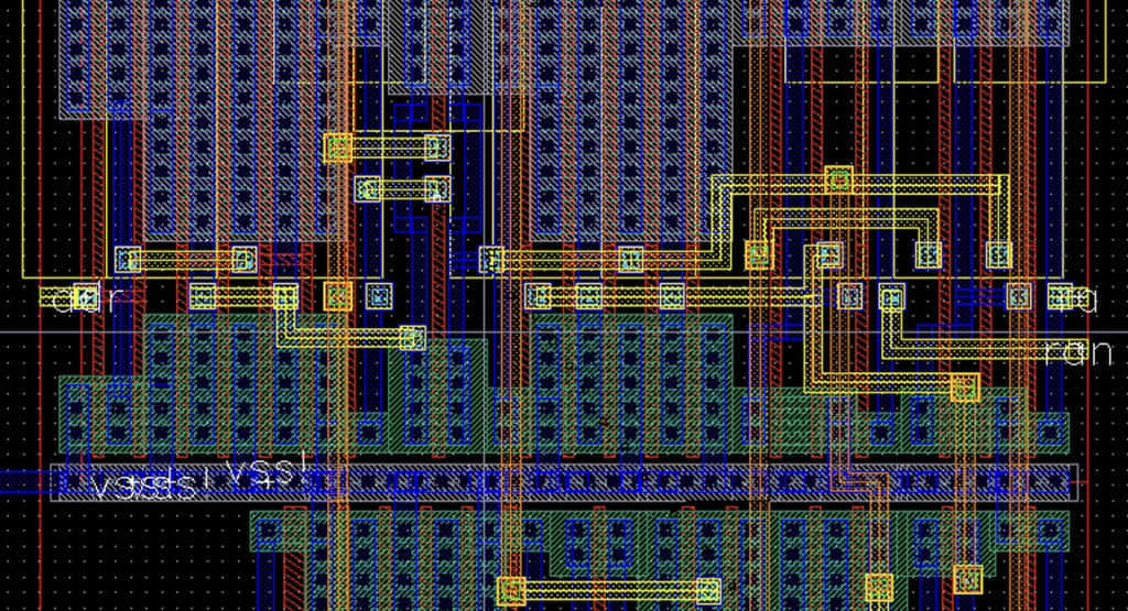
Figure 3: A design layout
4. Clock Tree Synthesis:
In digital circuits, synchronization relies on a crucial element: the clock signal. Clock tree synthesis entails constructing a hierarchical distribution network for the clock signal, guaranteeing simultaneous reach to all components.
Picture a conductor directing a symphony—the clock signal ensures seamless collaboration among all chip components. Two CTS methodologies exist: Symmetric Tree Architecture and Mesh Architecture.

5. Physical Verification:
Before sending the design for fabrication, engineers conduct thorough checks. These ensure the layout adheres to manufacturing constraints and rules. It’s like a final inspection before building construction, ensuring compliance with safety standards.
– The steps of Physical design flow are shown in the picture below
- Design Rule Check (DRC): Ensure that the layout meets the constraints required for manufacturing
- Electrical Rule Check (ERC): Check design for electrical connections that can be problematic Examples: Shorts/Open, Floating Gate, Floating Nets etc.
- Layout versus Schematic (LVS): Verifies whether the layout corresponds to the original schematic (netlist) of the design

Figure 6. Steps involved in Physical verification
Read More: First NPTEL Course that Covers the Entire IC Design Process from RTL to GDS
Conclusion:
Physical design is the bridge that connects the conceptual world of digital design to the tangible reality of integrated circuits. The demand for skilled physical design engineers is on the rise. This is fuelled by the continuous evolution of technology and the increasing complexity of semiconductor devices.


