Introduction
Have you ever wondered how GPUs, those powerhouses of modern computing, come into being? Well, wonder no more because we are diving headfirst into the world of GPU architecture, armed with nothing but curiosity and a willingness to learn. Let’s embark on this captivating journey into the creation of a GPU from scratch.
Follow us on Linkedin for everything around Semiconductors & AI
Step 1: Understanding the Fundamentals
The first step to understand modern GPUs is with a deep dive into their architecture. This is more challenging than expected. Since GPUs are largely proprietary technology, detailed learning resources are scarce.
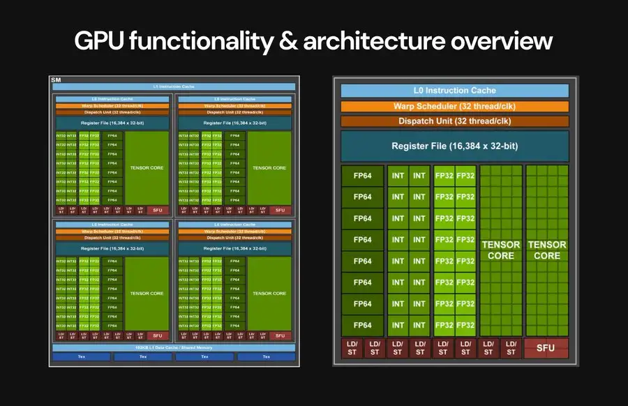
First we have to tackle the software side by exploring NVIDIA’s CUDA framework. This will introduce the Single Instruction Multiple Data (SIMD) programming model used in GPU kernels. Equipped with this knowledge, we delve into the core GPU components:
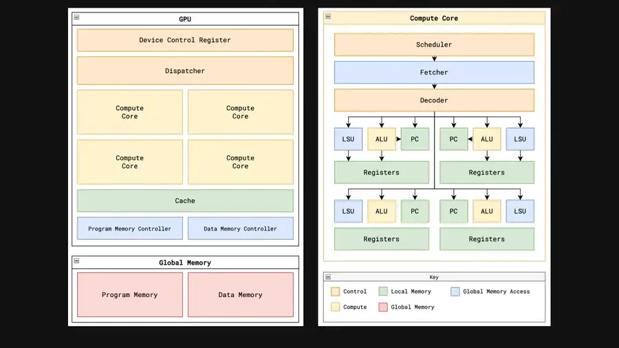
- Global Memory: This external memory stores data and programs, but access is a major bottleneck in GPU programming.
- Compute Cores: The workhorses of the GPU, executing kernel code in parallel threads.
- Layered Caches: Minimize global memory access by storing frequently used data.
- Memory Controllers: Manage access requests to global memory to prevent overwhelming the system.
- Dispatcher: The GPU’s control center, distributing threads to available compute cores.
Zooming in on individual compute cores, we discover:
- Registers: Dedicated storage for each thread’s data.
- Local/Shared Memory: Shared memory space for threads within a block to exchange data.
- Load-Store Unit (LSU): Handles data transfer between registers and global memory.
- Compute Units: Perform calculations on register values using ALUs, SFUs, and specialized graphics hardware.
- Scheduler: The heart of the core’s complexity, managing resources and scheduling thread instruction execution.
- Fetcher: Retrieves instructions from program memory.
- Decoder: Converts instructions into control signals for execution.
Read More: 8 Companies Poised to Benefit Significantly from the AI Boom – techovedas
Step 2: Creating Our Own GPU Architecture
Following the foundational knowledge, I create a custom GPU architecture. The objective? To craft a stripped-down GPU, showcasing the core functionalities and removing extraneous complexities. This would serve as a simplified learning tool for others seeking to grasp GPUs.
The Design Process: Devising this architecture proved to be an exceptional exercise in pinpointing the essential elements. Throughout the building process, several iterations were made as my understanding grew.
Key Learning Areas: The design specifically emphasized these crucial aspects:
- Parallelization: How the hardware executes the Single Instruction, Multiple Data (SIMD) paradigm.
- Memory Access: How GPUs address the challenges of accessing vast amounts of data from limited-bandwidth memory.
- Resource Management: How GPUs optimize resource utilization and efficiency.
A Focus on General-Purpose Computing: To encompass the broader applications of GPUs in general-purpose parallel computing (GPGPU) and Machine Learning (ML), I opted to prioritize core functionalities over graphics-specific hardware.
The Final Design: After numerous refinements, I arrived at the following architecture, implemented in my actual GPU (presented here in its most simplified form).
Read More: Google Reaches Unprecedented $2 Trillion Market Cap Milestone – techovedas
Step 3: Crafting a Custom Assembly Language
To achieve maximum performance, we need our GPU to understand kernels written using the Single Instruction, Multiple Data (SIMD) programming model.
Solution: To design a custom Instruction Set Architecture (ISA) specifically tailored for the GPU. This ISA would serve as the foundation for writing these SIMD kernels.
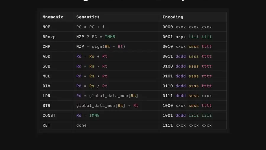
A Proof of Concept ISA: Inspired by the LC4 ISA, we create a streamlined 11-instruction ISA to enable writing basic matrix math kernels.
Instruction Breakdown:
- NOP: A no-operation instruction, simply increments the program counter.
- BRnzp: Enables conditional branching and loops using a special NZP (Negative, Zero, Positive) register.
- CMP: Compares values and sets the NZP register for conditional branching with BRnzp.
- ADD, SUB, DIV, MUL: Basic arithmetic operations to perform essential tensor computations.
- STR/LDR: Stores and loads data from global memory, providing access to initial data and storing results.
- CONST: Loads constant values directly into registers for efficiency.
- RET: Signals the completion of a thread’s execution.
Read More: How Gold Plays a Surprisingly Important Role in Nvidia’s GPUs – techovedas
Next Steps:
A detailed table outlining the exact structure of each instruction within this ISA will be provided below.
Step 4: Writing Matrix Math Kernels
Having defined our custom ISA, I developed two core matrix math kernels designed to run on the GPU. These kernels encapsulate:
- Matrix specifications: Define the size and type of matrices involved in the operation.
- Thread configuration: Specify the number of threads to be launched for parallel execution.
- Computation logic: Code executed by each thread, typically involving SIMD instructions, basic arithmetic, and load/store operations.
The first kernel demonstrates matrix addition between two 1×8 matrices using 8 threads. It showcases the power of SIMD instructions, fundamental arithmetic operations, and load/store functionality within the ISA.
The second kernel tackles matrix multiplication for 2×2 matrices using 4 threads. It delves deeper, incorporating branching and loop constructs within the kernel code.
These fundamental matrix operations pave the way for more complex computations on the GPU, which are the cornerstone of modern graphics and machine learning applications.

Step 5: Building The GPU in Verilog
The real test begins with translating the design into Verilog, the hardware description language. This proves to be the most challenging but ultimately rewarding step.
- Memory Mishap: The initial attempt with synchronous memory was a detour. GPUs are all about overcoming memory latency, and synchronous memory wouldn’t cut it. It is redesigned with asynchronous memory and memory controllers.
- Warp Speed… Whoa There!: We dive into a complex warp scheduler. This over-engineering highlighted the importance of understanding project goals before diving headfirst. The irony? It took building it to see why it wasn’t needed!
- Taming the Threads: The true reward comes from the lessons learned from understanding the control flow:
- Memory Bottlenecks: Struggling with memory access issues hammered home the crucial role of memory management in GPUs.
- The Power of Queues: When multiple cores tried accessing memory simultaneously, the need for a request queue system became crystal clear.
- The Allure of Optimization: Implementing simple scheduling approaches tells us how advanced techniques like pipelining could further optimize performance.
The final execution flow for a single thread, detailed in the image, mirrored a CPU’s. After countless revisions. – running matrix addition and multiplication kernels. Witness the GPU churning out the correct results.
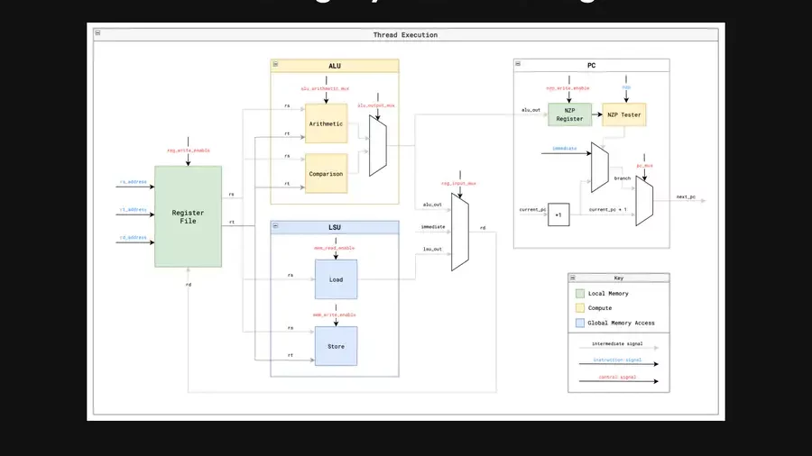
This step wasn’t just about building a GPU; it was about forging a deep understanding of its complexities and the power of overcoming challenges.
Read More: Threat for Spotify: Amazon Maestro Learns Your Taste and Create Custom Music – techovedas
Step 6: Chip Layout and Fabrication
With the Verilog code complete, it is time for the ultimate test: transforming the design into a real, physical chip. This involves running the design through a specialized Electronic Design Automation (EDA) flow to create the final chip layout.
Targeting the Skywater Process
We choose the Skywater 130nm process node for this project. This step serves as a crucial reality check in the design process.
From Simulation to Silicon: The GDS Challenge
A design that functions flawlessly in simulation can hit a major roadblock when translating to a physical layout with GDS files. This conversion process exposes any issues that might prevent the chip from actually working.
Conquering Design Rule Checks (DRCs)
During this stage, We encounter challenges with our design failing to meet certain Design Rule Checks (DRCs) defined by the OpenLane EDA flow. These checks ensure the layout adheres to the manufacturing guidelines of the chosen process node (in this case, Skywater 130nm). We have to make adjustments to my GPU design to address these issues.
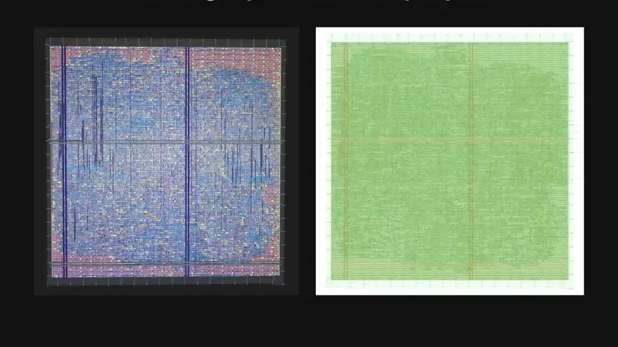
Success! A Hardened Layout and GDS Files
Through perseverance, We achieve a finalized and “hardened” version of the GPU layout, complete with the necessary GDS files ready for submission (see image below).
Read More: How Gold Plays a Surprisingly Important Role in Nvidia’s GPUs – techovedas
Conclusion
This expedition into the world of GPU architecture has been an odyssey of exploration and education. We began with a thirst for knowledge, delving into the core functionalities of these computational powerhouses. We then embarked on the exhilarating challenge of crafting a custom GPU, stripped down to its essential elements for maximum learning impact.

