Introduction
Navigating the complex terrain of semiconductor development, a notable transformation unfolds—the transition from conventional 2D to cutting-edge 2.5D & 3D IC packaging. This paradigm shift not only unveils the challenges posed by Moore’s Law and the constraints inherent in 2D methodologies but also promises enhanced efficiency and a realm of capabilities yet to be fully explored.

In this blog we will take you through a journey of IC packaging as we explore the why and how behind the evolution from two to three dimensions in the world of integrated circuits.

Join Our WhatsApp News for updated information on semiconductors & AI
What is IC packaging?
Integrated Circuit (IC) packaging is a crucial step in the semiconductor manufacturing process that involves enclosing a semiconductor die (the actual integrated circuit) in a protective and often functional package. This packaging serves several purposes, including providing protection from environmental factors, heat dissipation, electrical connections, and sometimes additional features such as signal conditioning or power delivery.
In the semiconductor manufacturing flow, IC packaging typically comes after the fabrication of the actual semiconductor device. The process involves taking the bare semiconductor die, which is usually a small, fragile piece of silicon containing the integrated circuit, and placing it into a package that provides the necessary support and connectivity.
Read More: UMC Launches W2W 3D IC Project, Revolutionizing Edge AI Applications
A real-life analogy to understand this process:
Imagine you have just baked a delicious and intricate cake (equivalent to the semiconductor device). The cake represents the integrated circuit, and it’s the result of careful and precise work in the kitchen (analogous to semiconductor fabrication).
However, your cake is still vulnerable to the elements, and you need to transport it to a party across town. You wouldn’t want it to get damaged, so you need to package it appropriately. You put it in a sturdy cake box (analogous to the IC package) that not only protects the delicate structure of the cake but also provides a means to carry it easily.
In this analogy:
- Baking the Cake (Semiconductor Fabrication): This is the process of creating the integrated circuit on the semiconductor wafer.
- Packaging the Cake (IC Packaging): After baking the cake, you protect it by placing it in a box. Similarly, after fabricating the semiconductor, you protect the bare die by placing it in a functional package.
- Transporting to the Party (Integration into Devices): Now, you can transport and serve the packaged cake at the party. Similarly, you can integrate the packaged semiconductor into electronic devices, such as smartphones or computers.
In both instances, packaging safeguards the delicate core (cake or semiconductor) and facilitates external connections (transport or circuit board link). Semiconductor packaging also often incorporates heat dissipation features to maintain integrated circuit performance.
In the evolution from 2D to 3D, packaging transforms from a flat configuration to layered structures. This process aims to overcome limitations in size, power consumption, and signal transmission, heralding a new era in semiconductor technology.
Read More: Explained: What the hell is 3D IC packaging?
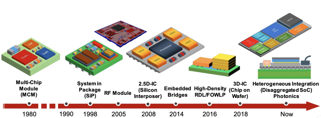
2D 2.5D & 3D Packaging
The Era of 2D Packaging
In 2D IC packaging, arrange individual chips or dies side by side on a substrate or printed circuit board (PCB). Interconnect them using wire bonding or flip-chip technology.

However, as the number of transistors on a chip increases (following Moore’s Law), the interconnect length and complexity also increase, leading to higher power consumption and slower signal transmission.
Some problems faced in 2D packaging are:
- Limited Integration: In 2D IC packaging, discrete devices for different functions such as high-performance logic, lower-performance logic, memory, and analog/RF each existed in their own chip packages. This setup limited the achievable level of integration.
- Size and Weight: The resulting circuit board from 2D IC packaging will be larger, heavier, and consume more power
- Reliability: Every soldered joint on the board is a potential point of failure
- Performance Hit: There’s a significant hit in performance, because it takes a relatively long time for signals to propagate across the board from one chip package to another.
These limitations led to the development of 2.5D IC packaging.
Read more: Intel to Build First Overseas 3D Chip Packaging Facility in Malaysia
2.5D IC packaging
2.5D IC packaging is an incremental step from traditional 2D IC. Unlike 2D packaging, which places chips side by side on a substrate, 2.5D packaging involves placing two or more active semiconductor chips side by side on a silicon interposer.

This silicon interposer provides connectivity between the chips, achieving extremely high die-to-die interconnect density. This allows for finer lines and spaces compared to 2D IC packaging.
So, while 2D packaging has chips spread out on a single plane, 2.5D packaging begins to build up. This offers a middle ground between 2D and 3D packaging.
We can think of 2.5D IC packaging as a city with buildings of the same height, connected by bridges. Each ‘building’ is a chip that performs a specific function. The ‘bridges’ are silicon interposers that allow faster and more efficient communication between the buildings.
Examples of 2.5D IC packaging:
Intel’s Kaby Lake-G processor: This processor combines a CPU and GPU on a single package using Intel’s Embedded Multi-Die Interconnect Bridge (EMIB) technology.
AMD’s Radeon Instinct MI25X graphics card: This uses AMD’s Interposer Bridge (IFB) technology to connect multiple HBM2 memory stacks to a GPU.
NVIDIA’s Tesla V100 graphics card: This graphics card uses NVIDIA’s NVLink technology to connect multiple GPUs together.
Moore’s limitations & fundamental reasons to go for stacking of chips
Device Scaling: This involves reducing the size of the entire chip or package, which includes all the transistors, interconnects, and other components. Techniques like lithography and etching are used.
However, as we reach the limits of Moore’s law, device scaling becomes a challenge. Devices shrink at a slower rate, and the cost is much higher for the technologies, design, analysis, and manufacturing of these chips.
Physical Limitations: Since modules are placed side by side, adding more chips leads to larger area. There are practical limitations on how large you can make a device.
The photomask and reticle size ultimately determine a chip’s maximum size – roughly 25 to 27 millimetres on a side. So, physically, you cannot make a chip bigger than that.
Transistor Scaling: Since the number of transistors scaling has reduced, designers do not benefit from increased complexity by putting more and more devices into a single package.
These limitations of led to the development of 3D IC packaging.
Read more: How Chiplets Can Change the Future by extending Moore’s law
The Advent of 3D IC Packaging
3D IC packaging is like stacking books on top of each other. Each “book” or chip has its own function, and they’re connected vertically, like a staircase between books. This allows us to add more books in the same shelf space, making the system faster and more efficient. It’s like building skyscrapers in a city to save space.

3D ICs enable “more than Moore” integration, enhancing functionality in smaller spaces and reducing costs. These packages can accommodate various dies, including logic, memory, analog, RF, and MEMS, at different process nodes. They combine high-speed logic with older nodes for analog functions. This approach optimizes performance and form factors.
Thus, multiple devices can be integrated in a single die with larger space.
How 3D IC packaging is achieved – The technical terms
3D IC packaging is achieved through a process known as vertical stacking. This involves the use of traditional interconnection methods such as wire bonding and flip chip technology. The 3D packaging can be divided into 3D system in package (3D SiP) and 3D wafer level package (3D WLP).
- Think of 3D System in Package (3D SiP) like a multi-storey building where each floor is a different chip. They are connected by elevators (wire bonds or flip chip technology).
- 3D Wafer Level Package (3D WLP) is like a single large floor where different rooms (chips) are connected by doors (interconnects). The entire floor is built at once (wafer level processes), creating a packaged component base structure.
Both methods allow us to fit more chips in the same package, improving performance.
Examples of 3D IC packaging:
Samsung’s Exynos 8895 processor: This processor uses Samsung’s 3D Wafer-on-Wafer (WoW) technology to stack multiple dies on top of each other.
Apple’s A11 Bionic processor: This processor uses Apple’s Integrated Fan-Out (InFO) technology to embed memory chips directly into the processor package.
HiSilicon’s Kirin 980 processor: This processor uses HiSilicon’s CoWoS (Chip on Wafer on Substrate) technology to stack memory chips on top of a substrate.
Read More: The Fall of Intel: How an MBA CEO’s Short term thinking destroyed a semiconductor giant
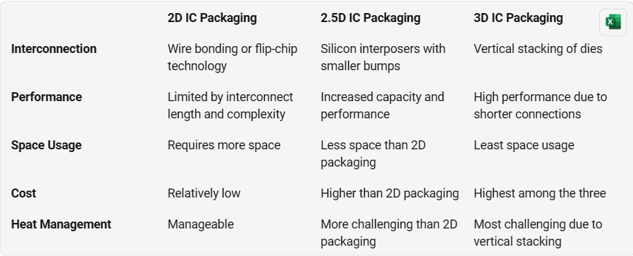
Difference between 2D, 2.5D & 3D IC Packaging
The terms 2D, 2.5D, and 3D IC packaging refer to different levels of integration and stacking of components in semiconductor packaging.
Let’s explore the differences between them:
2D IC Packaging:
Traditional or 2D IC packaging involves placing individual semiconductor components, such as chips, on a single plane or layer.
- Characteristics: In a 2D package, components are typically side by side on a flat surface, connected using wires or traces on the package substrate or printed circuit board (PCB).
- Advantages: 2D packaging is well-established, cost-effective, and widely used. However, it may face limitations in terms of space efficiency and performance as the demand for smaller and more powerful electronic devices increases.
2.5D IC Packaging:
In 2.5D IC packaging, multiple semiconductor components are still on the same plane, but there is an additional element of integration through the use of an interposer.
- Interposer: An interposer is a silicon or organic substrate that sits between the different semiconductor components. It provides a platform for connecting these components and can have additional features like through-silicon vias (TSVs) for vertical connections.
- Advantages: 2.5D packaging allows for better performance and power efficiency compared to 2D packaging. The interposer can enable higher bandwidth and shorter interconnect lengths, reducing signal delay and power consumption.
3D IC Packaging:
3D IC packaging involves stacking multiple semiconductor components on top of each other, creating a vertical integration of chips.
- Stacking: The stacking can be achieved using through-silicon vias (TSVs) or other vertical interconnects, allowing for communication between the stacked layers.
- Advantages: 3D packaging offers significant improvements in terms of space efficiency, performance, and power consumption. By stacking components, signal paths can be shorter, leading to faster communication between layers. It also enables the integration of heterogeneous technologies, where different types of chips can be stacked for specialized functions.
In summary, the main difference lies in the level of vertical integration:
- 2D IC Packaging: Components are on a single plane.
- 2.5D IC Packaging: Components are on the same plane, but an interposer allows for additional integration.
- 3D IC Packaging: Components are stacked vertically, enabling a higher level of integration and potentially improved performance and power efficiency.

AMD
AMD launched the Ryzen 7 5800X3D in 2022, bringing the world’s first processor with 3D V-Cache to market.

AMD’s 3D V-Cache is a technology that enables the company to vertically stack cache on a processor. This technology enables AMD to boost CPU memory without enlarging the die or reducing logic circuit size. It’s essentially a larger, secondary L3 cache that sits right on top of the CPU cores
Conclusion
Continuing technological advancements highlight the evolution of 2D, 2.5D & 3D IC packaging. It emerges as a solution to surpass the limitations posed by Moore’s Law and 2D packaging. It offers improved functionality, enhanced performance, and reduced costs, making it a key player in the future of semiconductor technology.


